
Comet64 Kit Assembly Instructions
This article describes how to assemble the Comet64 Internet Modem when you purchase it as a kit.
Parts List
Internet-Only Parts
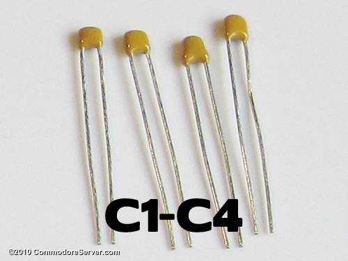
- 4x Ceramic Capacitors C1-C4
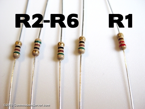
- 4x Resistors R2-R6
- 1 Resistor R1
- 2x Female headers/risers
- 1 User Port Connector
- 1 RJ-45 Ethernet jack
- 1 Printed Circuit Board
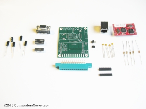
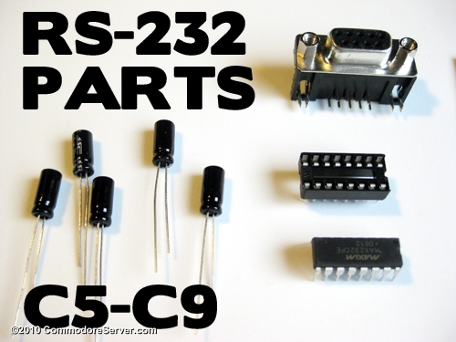
RS-232 Optional Add-on
- 5x Electrolytic Capacitors
- MAX232 IC
- IC Socket (optional)
- DB-9 male Connector
Assembly Tips
Soldering requires skill, patience and precision. Although the circuit board has a "solder mask", it is still possible to bridge connections with a blob of solder. Most of the solder connections are small, so make sure you have a clean, sharp soldering iron tip. The order in which you assemble the parts is not important. However, I have found that the order listed here is helpful and allows easier placement of parts.
I recommend reading this article in full so you get the full idea of assembly. At least read each step in full before assembling the parts for that step, just in case there are special instructions or procedures that you need to follow.
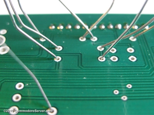
To help prevent things from falling out when you turn the circuit board over to solder, you can tape the parts down prior to flipping the board. For components, you can simply bend the pins in opposite directions, as shown here:
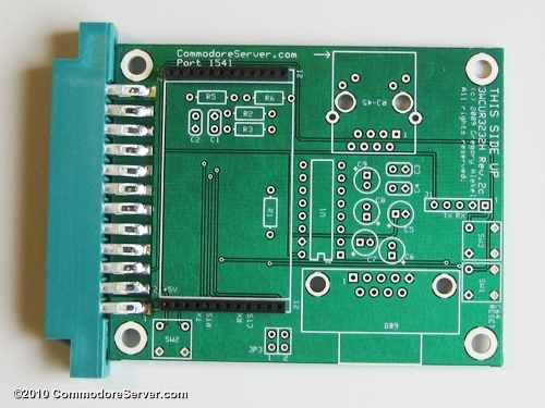
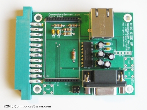
Attach the User port Connector to the PC Board
I typically put the printed part of the connector facing down to allow for a cleaner-looking top surface.
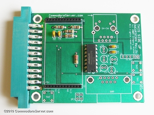
Connect the Two Female Headers
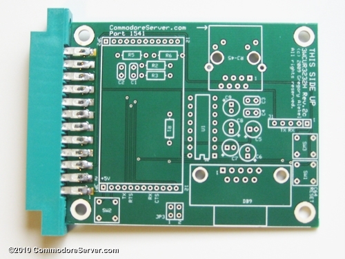
It is important at this point to take note of which side of the board is UP. Components should all be placed on the top of the board, which is the surface with the white printed silkscreen.
Be patient with this step. Pin 1 (the pin that attaches to the square) is slightly out of alignment with the rest of the pins (there is a larger gap between pin 1 and pin 2 than the rest of the pin spacing). It takes a little wiggling to get the connectors to fit right. I usually place pin 1 in (square hole) and then pull the connector toward the rest of the holes as I fit the other pins in. This technique will slightly bend pin 1 as the connector is being pulled into place. Do not pull too hard as to break the pin or bend it severely.
This was done to assist in keeping the part snug enough to remain seated when you turn the board over to solder the pins. I have never had one fall out, so you shouldn't need to tape the connector to the board before soldering.
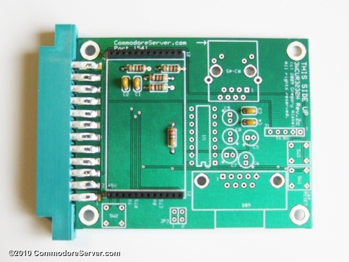
Attach All Resistors and Small Capacitors
One resistor sits alone while the other four are grouped together. It is an easy way to identify which resistor remains alone. Refer also to the picture in the parts list to identify proper placement.
There are four small, tan capacitors that are also grouped together. Place and solder these next.
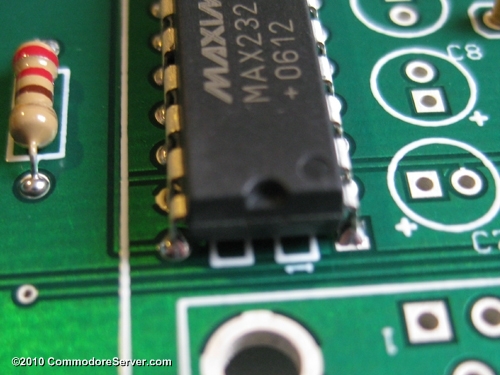
Attach the MAX Chip
If you are not assembling the RS-232 option, you may skip this step.
ICs typically have their pins bent out a little further than the holes allow for on the printed circuit board. You will have to straighten the pins in order for it to fit. Be extra careful when placing this component. Do not bend the pins too far - the pins may break off and you will not be able to connect the part. If you do happen to break the pins, do not attach the chip. The Internet portion of the board will still work without this part. You can order a new chip and place it later if you damage it.
Alignment of the chip is very important, too. The chip has a rounded notch on one end. The circuit board shows a rectangle with a notch on one end, too. Make sure the chip's notch is aligned with the circuit board's notch, as seen here:
You may use the IC socket if you are uncomfortable soldering the chip directly, although it will raise the chip high enough to possibly collide with the daughterboard above. Soldering a chip is fine if you have a low enough wattage (15-25 watts) iron or use heat sinks for each pin you solder. The choice is yours, but use caution if soldering the chip directly - excessive heat may damage the IC.
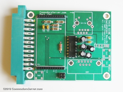
Solder Electrolytic Capacitors
If you are not assembling the RS-232 option, you may skip this step.
Placing these capacitors properly is important. The long lead of the capacitor is positive. Feed the long lead into the square hole (also marked with a +) for each capacitor and solder them in.
Attach the Jumper Header
This will be somewhat difficult - the holes for the jumper header are too small for a perfect fit, but with the proper technique, you can still make it fit. I like to place the board on a flat, sturdy surface and tap the part down with a small hammer. It can be tapped down to be flush with the bottom and then pushed through the rest of the way using a screwdriver or other device. You can avoid placing this part completely, by bridging the connection for JP3, jumper 1 since it is not used in this revision of the board. You can use one of the trimmings from your resistors or capacitors to jump and then solder it on the bottom side of the board. Or you can bridge the two holes with a blob of solder.
Attach and Solder RS-232 DB-9 Connector and RJ-45 Connector
These may take a little finessing if the pins are not perfectly straight. Be careful when inserting these parts - it is a tight fit. Avoid bending the pins and breaking them off. It is usually better to start with aligning the pins and then the larger mount pins. The larger parts will usually fall into place easier.
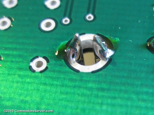
When soldering the DB-9 connector, it is not necessary to use a large amount of solder. A small dab on each side should hold the connector stable, as shown here. If it makes you feel better, go ahead and fill it in.
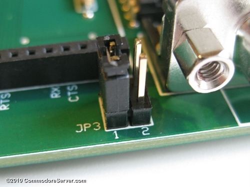
Attach Jumper on JP3
The jumper is not used in this revision of the board, but for proper operation, it is important to place it on pin 1, as shown here:
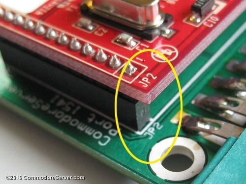
Insert the Daughterboard into the Risers
The red daughterboard fits snugly into the risers on JP1 and JP2. Be sure to align the board properly, as shown here:
Congratulations! Assembly is Complete
Now for the big test - does it work? A quick way to find out is to plug it in according to the directions in the Comet64 Installation Guide.
If it doesn't work, carefully review and check that all steps have been completed above. If you are still having trouble, contact me and I'll try to help solve the issue.


Leave a Comment
You must be signed-in to post comments.Responses